Hello Xeno World

I thought I would go over quickly how to make a very simple Xenomai user space application.  This is just a simple hello world program that will help use create a make environment for Xenomai applications.  Our goal here is not to do anything interesting, we just want to setup a cross-compiling environment for out Zynq development platform.

Before we start you should have to complete my tutorial about building Xenomai 3 for Zynq.  We are going to need to use our stage directory from that tutorial.  This directory contains libraries and helper scripts.  We will need the xeno-config script to help build our applications.  The config script holds all of our information about what we are targeting.  If we run it alone we should see something similar to the photo below…..

Screenshot from 2017-08-07 23-21-04Using this script we should have all the information we need to create our first Xenomai program.  All the source is located on github here. First let’s look at the makefile.

Screenshot from 2017-08-07 23-33-39

I created a variables PATH_TO_STAGE which holds the path to where your xenomai 3 libraries and scripts are located.  Change this in the makefile to match with your local system.  We’ll need to set the DESTDIR variable to this path so the cross compile tools can find our libraries during the build stage.  I haven’t added a clean option to this makefile since it’s very simple.  Feel free to add a clean option if you’d like, we’ll add that in the future tutorials.  The xeno-config script will hold all the information that we need to make sure we are building for the correct platform with the correct compiler and linker flags.  The other thing to note here is I have chosen the native skin, if you want the posix skin, vx skin or any other the other ones you would just change –native to the option of your choice.  You can list the options by running xeno-config.

Now on to our very simple cpp file.

Screenshot from 2017-08-08 00-43-49.png

Again this is available on git hub at the link I posted above, but all we are doing here is using the native skin and printing a message to the screen.  The function rt_printf is form the native Xenomai API and behaves like normal printf from plan libc.

All we need to do now is call make and we should see some build output and then our new executable file.  We can copy this to our sdcard and then boot our board.  I copied it to my ubuntu user home directory.  We should be able to plug the Zybo into a network and scp the file over (something for another post) but for now I’ll just copy to the sdcard.

Once we have booted our board we have to add the path to where our libraries are to the file /etc/ld.so.conf.  Each file in this directory will contain a path where linux will search for libraries for our executables.  For our xenomai libs we’ll need to add the line “/usr/xenomai/lib”.  Since I have vi installed on my target I created the file with vi, use which ever method you’d like.  Once that is done we need to run:

sudo ldconfig -v

Now when we try to execute your Xenomai program we shouldn’t get any missing library failures.  So now we need to execute our hello program using sudo and we should see our print.

sudo ./hello_xeno_world

Now we should see our print statement, and have our first realtime program running.  The goal of this short post was to create a simple Xenomai application and getting the build environment set up.  Going forward we will be doing some more interesting things then just printing to the console.


Getting Started With Xenomai 3 on Zynq

We’ve built on the last tutorials to have a full linux system running on our Zybo board (although all this will work with the Zedboard or MicroZed with small modifications).  We now are going look at using Xenomai to give our system realtime capabilities.  Most people associate realtime with speed, but that’s not necessarily true.  Although most realtime system are very fast the most important aspect of a realtime system is the deterministic behaviour that it provides.  It can guarantee that an event will happen at a certain time all the time, if it doesn’t then the system can fail.  A realtime system can be hard or soft.  Hard realtime systems are usually found in safety critical systems and can not fail, if it does there could be deadly results.  Soft realtime systems are more common, live streaming video is a great example of a soft realtime system.  If the system misses an deadline then the worst that can happen is the user sees a blip in the video or a couple of dropped frames.

Xenomai (cobalt core) is a dual kernel system that give Linux realtime capabilities.  It splits the system into two domains primary and secondary.  The primary domain is the realtime domain and this is where all of our realtime code should reside.  The secondary domain is the non realtime domain, it is usually is comprises of the Linux domain and it can use any of the Linux functionality.  The primary domain on the other hand can use a subset of Linux resources or else it may cause a domain switch to the non realtime domain.  We’ll go over more how Xenomai works in future tutorials as we go over userspace and kernel space code that interfaces with Xenomai.

Before we start building our Xenomai patched kernel let go over the things we should have completed by now:

  • FSBL or U-BOOT spl bootloader
  • U-BOOT bootleader
  • A root filesystem

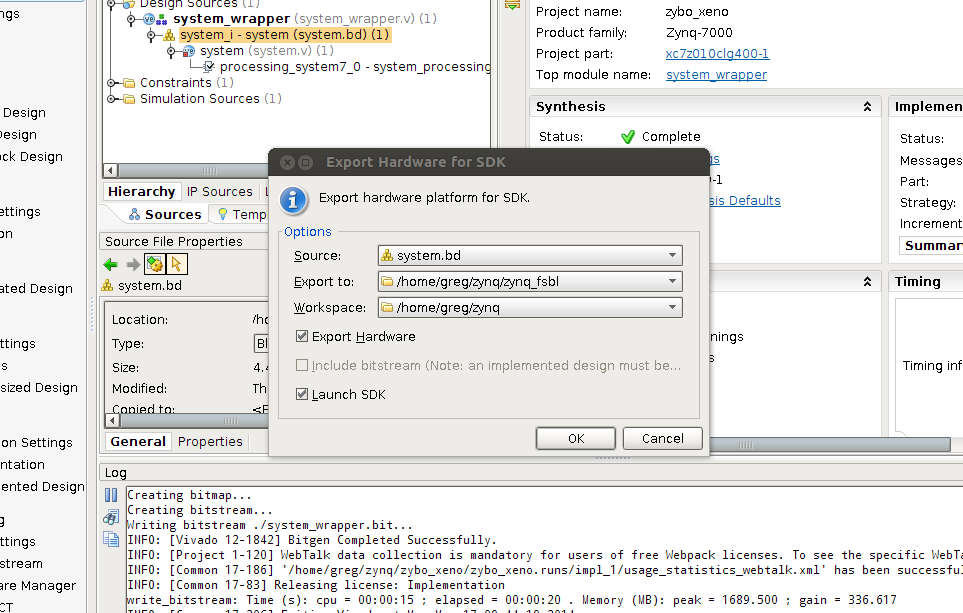
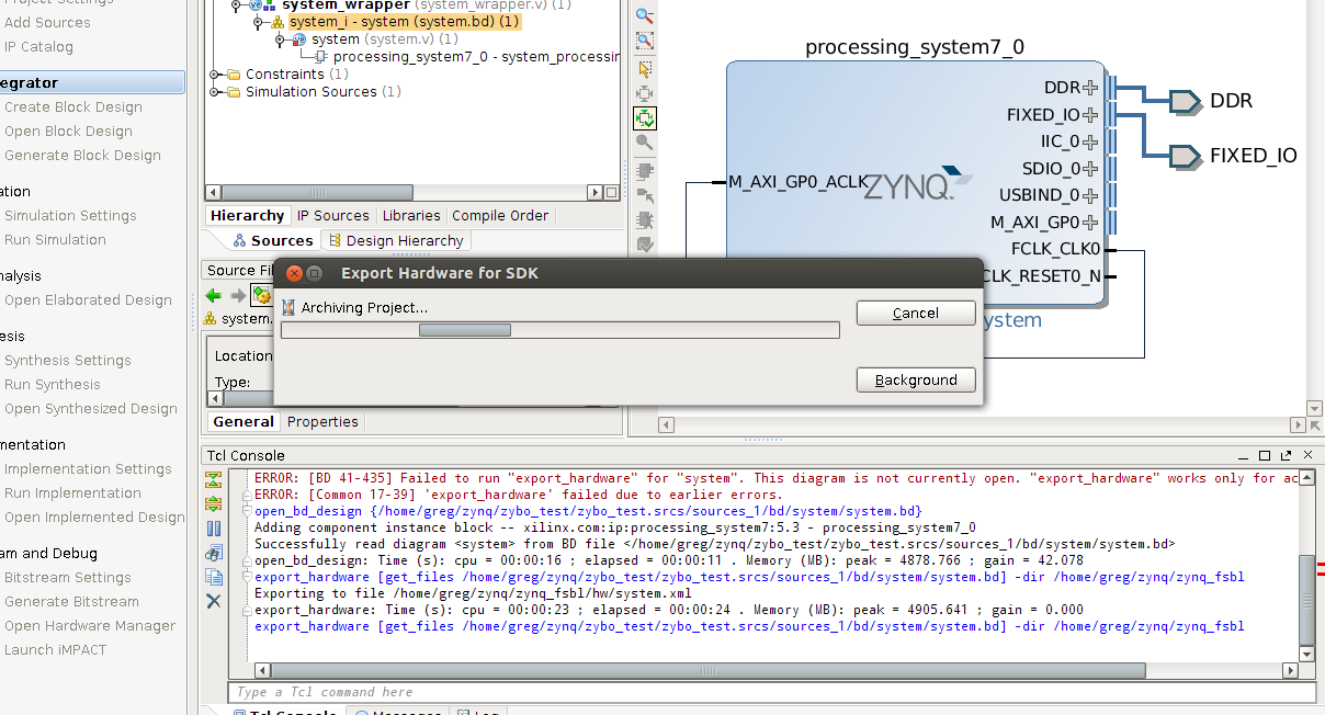
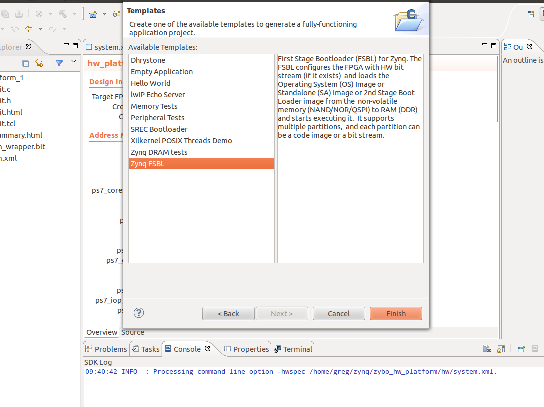
For our Xenomai system I would recommend using the Ubuntu 16.04 root filesystem that we built. Because we will be adding extra libraries I find it’s easier to go with something that is persistent.  I’ll go over how we would use Xenomai with a minimal root filesystem but because there are a fair amount of Xenomai libraries and utilities the RAM disk may be too large to manage in RAM.  If you’d like to use the Xilinx FSBL instead of u-boot spl that’s find remember that you’ll have to make a BOOT.bin image using the Xilinx SDK.

Now let’s get going on creating our Xenomai patched kernel.  I worked from the Xenomai git repos, you can also download the latest stable release.  Let’s go grab the Xenomai source code:

git clone git://git.xenomai.org/xenomai-3.git

Once we have that we need to go get our ipipe patch.  What is the ipipe you ask? The ipipe project is a open source project and is a patch onto the Linux kernel that gives Linux the ability to implement an executive running side-by-side.  This is what gives Xenomai the ability to run in the dual kernel mode.  It also makes it possible for the Linux kernel to have deterministic interrupt response times.  Most importantly this is the foundation that Xenomai is built on.  If you’d like to read more about the ipipe check out this link.

We don’t need to download the ipipe project just the patch for the Linux kernel.  In the past this patch was included in the Xenomai source tree but if the newer versions of Xenomai they’ve removed the patch from the source tree.  We now must go fetch the patch from this link.  Before we grab the patch we will need to figure out what kernel version we are going to compile.  In our previous tutorial we used 4.1.18 kernel, but this we’ve done that tutorial a new patch set has been released.  Therefore we will try to do our work using the 4.9.24 kernel which we have a ipipe patch for.  Let’s go ahead and download the ipipe patch.  I usually download it into the xenomai directory.  I’ve included a direct link here if anyone is having troubles downloading it.

So now we have the Xenomai source code, the ipipe patch that we need and we should have the Linux kernel source as well.  If you don’t we need to clone the stable tree like so:

git clone git://git.kernel.org/pub/scm/linux/kernel/git/stable/linux-stable.git

Now we need to make sure we have the correct branches checked out before we start trying to patch and build our Xenomai based kernel.   We will start with the linux stable tree, let’s checkout the 4.9.24 tag and make a branch for it.

git checkout tags/v4.9.24 -b zynq_xeno_4.9.24

So this should create a new branch for use that is based on the 4.9.24 kernel.  Next we need to make sure we are on the correct version of Xenomai. Change directory into our xenomai source directory.

git checkout tags/v3.0.5 -b xeno_3.0.5

This will create a local branch for us on the 3.0.5 tag which is the latest stable release of Xenomai.

Since we will be jumping around from directory to directory you may find it easier to create environment variables for the path to each directory that we need.  For me I used the following:

export XENO_HOME=/home/ggallagher/devel/xenomai-3
export LINUX_HOME=/home/ggallagher/devel/linux-stable
export LINUX_XENO_BUILD=/home/ggallagher/devel/linux-xeno-build

These are straight forward and you obviously should change them to point to the source on your own system.

We have our branches set up, we should make sure we have our build output directory created and we can start patching our kernel.  When we apply the ipipe patch if for some reason it fails or you forgot a build option then remember to clean the branch using the git clean commands or else we will have half patched files sitting there.  There doesn’t seem to be an option to do a dry run in the scripts help options so it’s basically all or nothing.

Change into your XENO_HOME directory and we’ll run the prepare kernel script to get our ipipe patch applied.  Make sure you remember where you downloaded your ipipe patch to, since we will need it in this step.

./scripts/prepare-kernel.sh --arch=arm –ipipe=../ipipe_patches/ipipe-core-4.9.24-arm-2.patch --linux=$LINUX_HOME

I saved my ipipe patch in a directory called ipipe_patched at the same level as my Linux and Xenomai directories.  This will succeed if we see no errors stating a chunk couldn’t be applied.  If you do see that check to make sure you’ve checkout the correct branch and are applying the correct patch.  If you found our mistake then make sure to use the git clean commands to clean out the linux source directory.  Worst case post your results in the comments and I can see if I can help.

Next we need to do our kernel configuration step.  Same as the tutorial before, let’s cd into our Linux directory and execute the following command.  Again remember to copy the zynq defconfig back into our Linux tree since it doesn’t exist in mainline.

make ARCH=arm CROSS_COMPILE=arm-linux-gnueabihf- O=$LINUX_XENO_BUILD xilinx_zynq_defconfig

Here we see exactly why we learned to build the mainline kernel.  We did so because we want to work with a kernel tree version that can easily have the ipipe patch applied on top of it.  We are going to have to make some custom configurations in our menuconfig step.  When we execute this command:

make ARCH=arm CROSS_COMPILE=arm-linux-gnueabihf- O=$LINUX_XENO_BUILD menuconfig

We are going to see some extra configuration options for Xenomai.  We will also see some warnings advising us to turn off frequency scaling and another warning that I believe is about page faults.  To turn those off we need to turn CPU frequency scaling off and turn off the CMA allocator.  Frequency scaling can be found under CPU Power Management -> CPU Frequency Scaling ->  then type N to exclude this option.  To turn off the CMA allocator go to Kernel Features -> hit N over the contiguous memory allocator.  The next option we have to disable most of the irq tracing.  If we leave this enabled we get a error on boot saying that it has detected a deadlock.  The output should look something like this.

[    0.579081]
[    0.585100]        CPU0
[    0.587595]        ----
[    0.590088]   lock(timekeeper_seq);
[    0.593615]   <Interrupt>
[    0.596280]     lock(timekeeper_seq);
[    0.599979]
[    0.599979]  *** DEADLOCK ***
[    0.599979]
[    0.606087] 1 lock held by swapper/0/0:
[    0.609955]  #0:  (timekeeper_seq){-?.-..}, at: [<c0080048>] __tick_nohz_idle_enter+0x28/0x42c
[    0.618555]

The system will still boot and work but I’m pretty sure this error message will come back to haunt us in the future.  So let’s take care of it now.  In menuconfig we need to turn off some of the kernel hacking features.  In the kernel hacking section I turned everything off except for kgdb, which I figured it is a good option to keep if we can.  Searching through the Xenomai mailing list is a great way to get some information about this issue and what features need to be turned off.

We are now ready to build out Xenomai patched kernel.  Make sure we’ve switched into our linux source directory.

 make ARCH=arm CROSS_COMPILE=arm-linux-gnueabihf- O=$LINUX_XENO_BUILD UIMAGE_LOADADDR=0x8000 uImage modules dtbs 

So we should have no problems building the kernel and after that’s complete will install the modules into our root filesystem.  Once we see our kernel has compiled successfully, we can do the following:

make ARCH=arm CROSS_COMPILE=arm-linux-gnueabihf- O=$LINUX_XENO_BUILD modules_install INSTALL_MOD_PATH=../zynq_modules/

Your module install path should be a directory where we can temporarily store the modules until we can add them to our root filesystem.  We could do it all in one step but it’s sometimes easier to explain the process this way.  Once you’ve executed that command you should see something that looks sort of like this:

INSTALL crypto/drbg.ko
INSTALL crypto/echainiv.ko

There will be some others, but it’s listing these modules as ones that the kernel can load dynamically on the fly.  We can either load them manually as we need them out add them to the module list for the kernel and have them loaded at boot.  We’ll leave this subject for now and come back to it once we’ve finished building Xenomai.  We need to install these modules into our root filesystem so the kernel can find them on boot.  We don’t need to do this right now to get our Xenomai install going but we will revisit this later when we add a wifi dongle to our system.

We now need to create the Xenomai libraries and tools that our system will need to run.  Since we built this from git we need to do this step.  If you ended up using a zip file you can skip ahead to where we build the arm libraries.  Let’s go back to our Xenomai source tree and we need to execute the following command.

./scripts/bootstrap 

This will get the Xenomai source ready to build our tools and libraries.  Make sure you have autotools and autoconf installed or else this next step will error out.  I haven’t really listed all the tools we need on our host system, I’ll leave that to the user as you get errors make sure you google them and see if you are missing any host side tools.  We want to build our libraries and tools to match our target system.  We have to make a directory to store the generated make files.

mkdir -p xeno3_build

Now let’s switch into that directory and we will generate the configuration and makefiles that we need to build the xenomai libraries and tools.

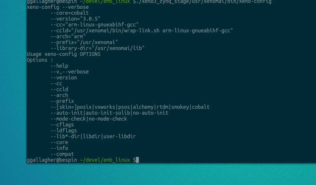
../xenomai-3/configure CFLAGS="-march=armv7-a -mfpu=vfp3 -mfloat-abi=hard" LDFLAGS="-march=armv7-a" --build=i686-pc-linux-gnu --host=arm-none-linux-gnueabi --with-core=cobalt --enable-smp --enable-tls CC=arm-linux-gnueabihf-gcc LD=arm-linux-gnueabihf-ld

If we look at this link here we can see all the options that we can include when configuring the tools to build.  Since the Zynq platform is compiled with the hard floating point toolchain and this isn’t an option for the –host option we will have to supply the CC and LD options to tell the tools what the toolchain prefix is.  The –host flag may be slightly misleading but that’s okay, just remember the –host flag refers to the target you are building for not the host environment you are building on.

We now should have a directory that is full of our configuration and makefile that we need to build our libraries and tools.  We will need to build them into a stage directory and then install them into our root filesystem.  I usually keep these outside of the root filesystem just so I can keep it clean but it’s not necessary.

make DESTDIR=/home/ggallagher/devel/emb_linux/xeno3_zynq_stage/ install

You could do this as two steps and do the install step as root and then install it into your root filesystem but because I’m keeping my Xenomai tools and libraries separate I don’t do that step as root.

If everything has gone well we should have a Xenomai patched kernel and Xenomai libraries and tools that will be needed for our target.  We are now ready to install these onto our sdcard and get the system ready to boot.

First let’s get our uImage from the Linux build directory and copy that over to the BOOT partition of our sdcard.  Next we can reuse our rsync command and copy over the Xeomai libraries and tools to our target root filesystem.

sudo rsync -aAXv <path_to_your_xeno_lib>/* /path/to/mount/point/

Once we have our patched kernel and libraries on our sdcard we can go ahead and see how we did.  Hopefully everything should boot fine and we can move on to calibrating our system and running the latency tests.

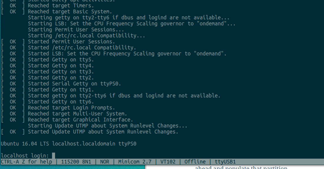
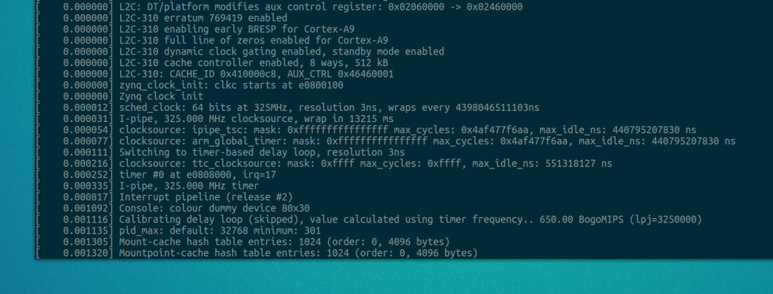
Let’s boot our board.  You should have it connected to a terminal program such as minicom so we can use the shell we are going to spawn over the uart.  Once the board boots we can log in and examine the dmesg logs.  We could look at the early printk as well and we should see some of the Xenomai initialization.

Screenshot from 2017-07-15 21-26-03.png

Let’s login as root since we will be executing some programs that need root privileges to run.  The first thing we are going to do is run the latency tests and see what results we get with all the default parameters.

/usr/xenomai/bin/latency

Once we run this command the latency test will start to run and print out some statistics about the latency on the system.  Below is what you may see on a non-calibrated system:

Screenshot from 2017-07-15 21-14-24

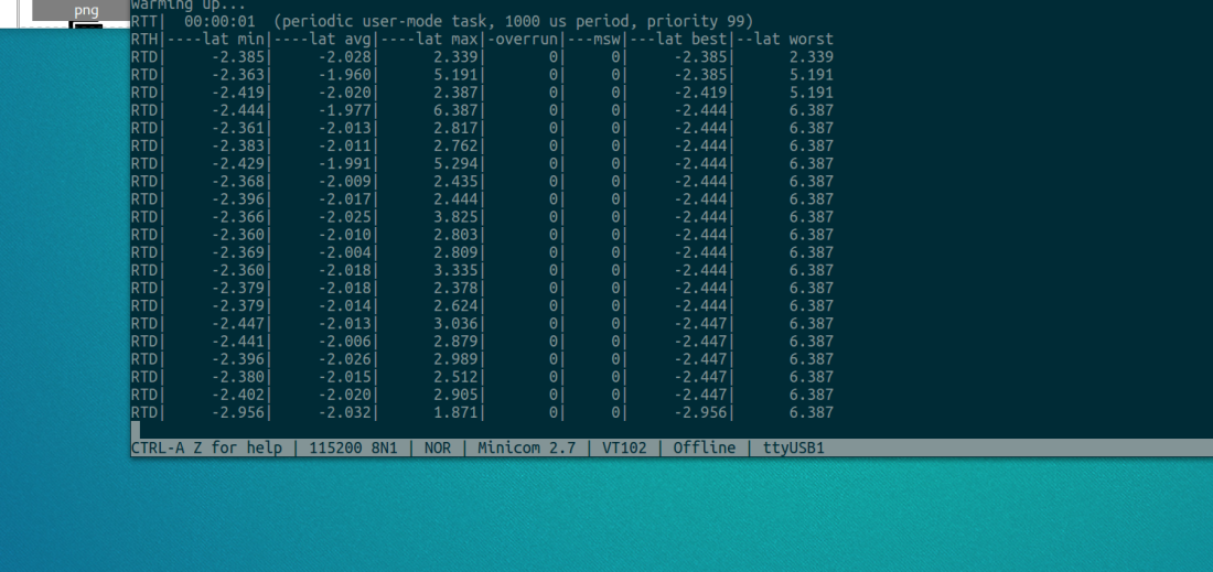
Our latencies are negative for some reason, which is confusing because that can’t be correct.  After a little bit of digging on the Xenomai mailing list we find this is normal.  From what I found searching online and the Xenomai mailing list in Xenomai 2 we need to decrease the /proc/xenomai/latency value until the minimum latency never drops below zero and at the same time we need to keep the worst-case as close to zero as possible.  We can change this value by echoing a value into

/proc/xenomai/latency

This will also work for Xenomai 3, after playing with this value we see the latencies on the system start to look more sane.  This however isn’t the best way of calibrating the system.

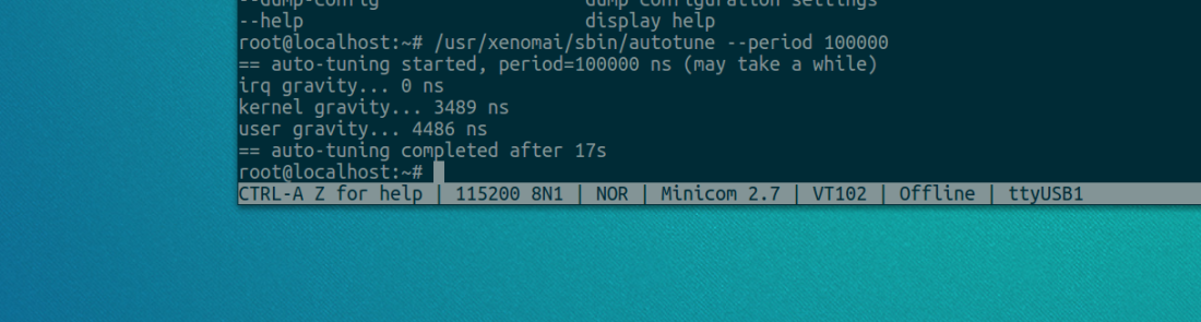
In Xenomai 3 we can use the autotune utility to calibrate our system.  This was not previously available in Xenomai 2.  What the autotune utility does is determines the correct gravity values.   A gravity values is the shortest time our platform (Zynq in our case) needs to deliver an interrupt to a Xenomai interrupt handler, a RTDM (kernel space) task or a Xenomai user-space task.  It will differentiate timers by the context they activate, this ensures the context will be activated as close as possible to the ideal time. There are three contexts, IRQ which is the Xenomai subsystem before the kernel, the kernel space and then user space.  These values can be set in the file /proc/xenomai/clock/coreclk on Xenomai 3.   After this utility is run the system will retain the final values until the next reboot.  The autotune documentation can be found here.   These value can be specified in the config variables specified in the documentation or the autotune utility should be run when the system starts.

To run this utility we can specify a couple different options that will let us calculate either each of the gravity values or all of them.  We need to also give sampling period.  We can specify other flags as well which I won’t go over now, but you can specify the –help flag to see what are valid arguments to the utility.  For my system I wanted to get all three values so I didn’t pass any arguments about what gravity I wanted.  If you don’t specify any it will do all three.  I also gave the smallest sampling period I could.  Too small of a sample period will cause the system to lock up.  The default value for the sampling period is 1000000, so I ran the test numerous time reducing the number as I went.  I finally finished on 10000 as my sampling period and I was able to complete the tests in about 17 seconds.

Screenshot from 2017-07-15 21-23-10.png

We now have our gravity values and we can go ahead and run our latency tests again.

Screenshot from 2017-07-15 21-23-53

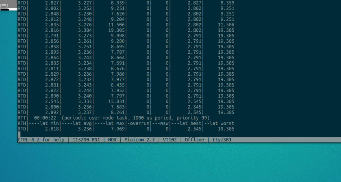
We can now go ahead and run the xeno-test utility.  This test will run our latency tests with load on the system.  We can get a good idea of what type of latency our system will have at the best and worst case.  This should give us a good idea of how our system will perform under load.  If you see hight latencies then you should checkout the trouble shooting guide here.

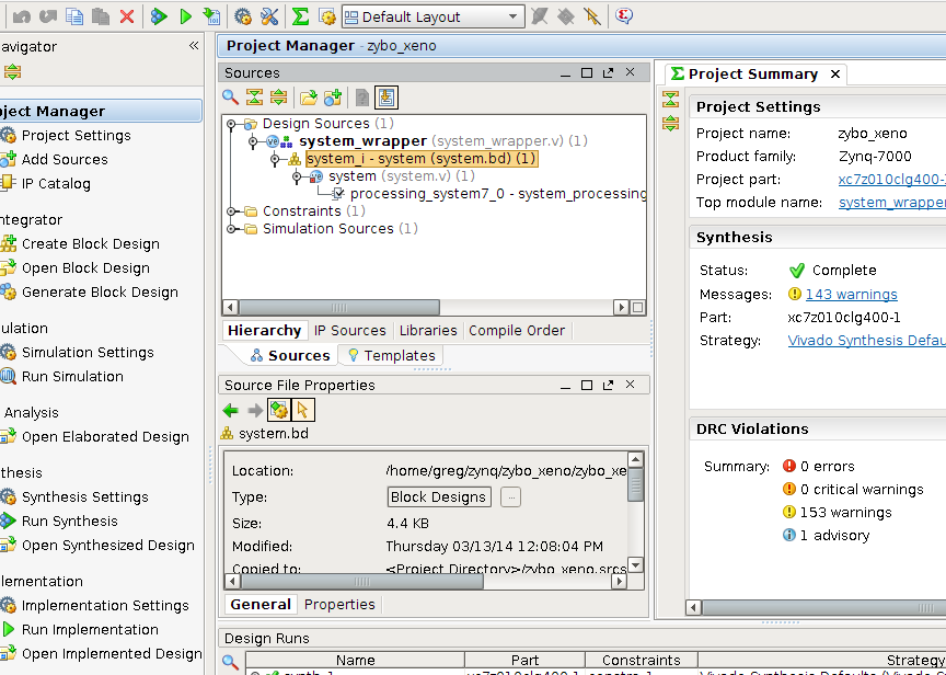
Our base Xenomai system is now ready to start creating some realtime applications on.  I’ll go over creating RTDM drivers and application level RT code in the next few tutorials.  In the next few posts we will be looking at creating a design for the PL, the RTDM driver to control our hardware and then creating some user space code to interact with it.
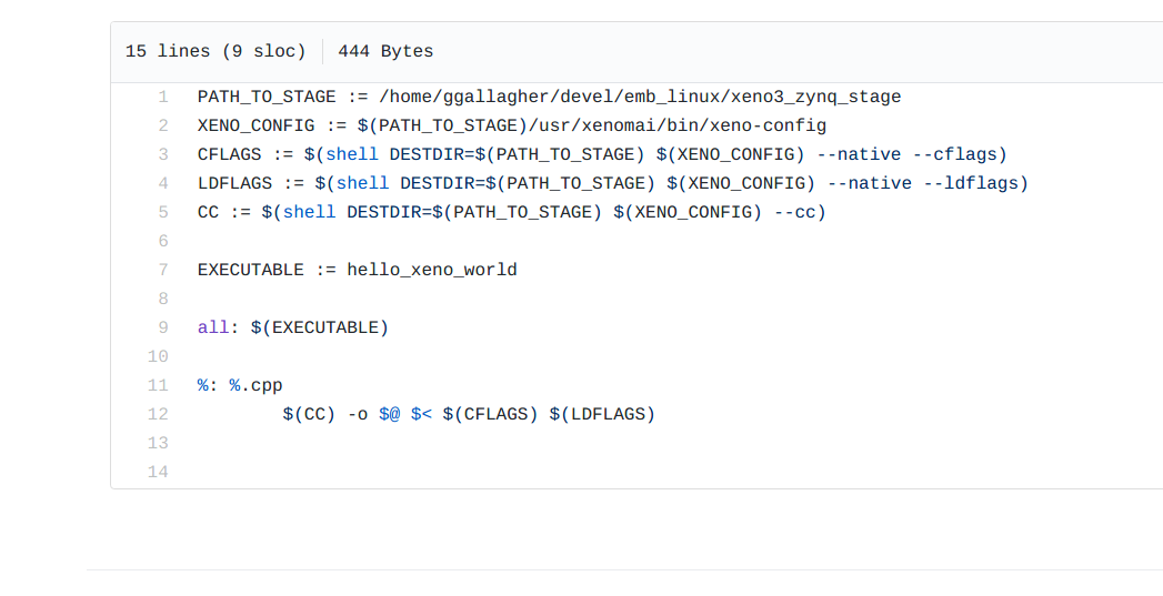
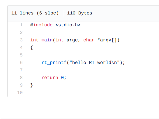
 

Creating A Ubuntu Xenial 16.04 rootfs for Zybo and Zynq

In one of my previous blog posts we went over how to make a minimal (sort of) root filesystem using buysbox.  This is great is you don’t need a package manager and want to built all our utilities and frameworks from source yourself. But if you would rather use a distribution to install packages and tools then then using a Ubuntu core distribution would be a good option.

Ubuntu base is basically a small Ubuntu root filesystem that only includes a command line interface.  It’s great starting point for any embedded system.  Even if you need a GUI X11 can be installed and configured.  Ubuntu base does not include a kernel, we need to provide that so it’s not as easy as the distributions you’d download and install on a laptop or desktop.

Before we get started please take a look at this page which basically already does what I’m about the explain.

Let’s download the ubuntu 16.04 Xenial for arm from here, we will need to download the following file ubuntu-base-16.04-core-armhf.tar.gz.

Make a directory where we will be creating our root filesystem, this is what I did on my system

mkdir -p zynq_xenial_rootfs

Now we need to uncompress the base system that we downloaded.  We can uncompress it into the directory we just made.

cd zynq_xenial_rootfs
sudo tar xf ubuntu-base-16.04-core-armhf.tar.gz

In our directory there should be the skeleton of the root filesystem with the correct permission since we uncompressed with sudo.  We still need to configure our serial port to have show our terminal output.  We’ll also create a chroot jail to test out our root filesystem and also install an utilities we may need.  To do this we will need to install qemu.

sudo apt-get install qemu-user-static

So you may be wondering why we want to create a chroot jail using qemu? I’ve used this method when I don’t have access to ethernet on my target board.  There may be situations where you can’t connect to wifi or there is no wired network that allows random devices to optain an IP address.  In these cases we can create our chroot jail and install any packages we need to get moving.

sudo cp $(which qemu-arm-static) zynq_xenial_rootfs/usr/bin/

Next, we are going to bind our hosts systems proc directory to our root filesystem.  This simply allows our chroot file system to use the hosts proc directory.  There is no harm in this and we can safely unmount it when we are done.

sudo mount -t proc proc zynq_xenial_rootfs/proc

We also need to set up the resolv.conf file, we will copy the one from our hosts system over.

sudo cp /etc/resolv.conf zynq_xenial_rootfs/etc/resolv.conf

We can now start our simulated chroot jail by executing the following command

 sudo chroot zynq_xenial_rootfs /bin/bash

We should now see the # sign to show we are logged in as root, we can use the exit command at any time to exit the chroot jail.

There are a couple things we will do using the chroot jail that will help when we first boot into our embedded Linux system.  We will set the root password, create a non-root user and install a couple of packages.

First let’s set the root password

passwd root

Enter the password that you’d like to use for root

Now we can create a non-root

adduser ubuntu

Then you’ll be asked to set a password for the new user.  Now that we’ve set up some users you are pretty much ready to use your system.  Since this system is Ubuntu (debian) based we can try using the package manager to install some utilities we will need.  Let’s try install python3,

apt-get install python3
apt-get install wireless-tools
apt-get install vim
apt-get isntall sudo

I’m assuming you are still logged in as root if not add sudo in front of this.  Install any other packages that your system may need.

One package we will need to install is the udev package.  For some reason it’s not included in the base image and will cause a fair amount of headaches when we are trying to spawn our serial console.  Let’s go ahead and install that, we will see some warnings in the output but we can ignore them.  The warnings are a result of us using a chroot jail.

apt-get -y install udev

In order to log into our system though the uart of the Zybo we need to configure the console login process for ttyPS0 which is UART0 on the ARM processor.  To do this we need to create a file called /etc/init/ttyPS0.conf. 

vi /etc/init/ttyPS0.conf

This file will spawn a console over our uart port on start up, the contents of the file should look like:

start on stopped rc or RUNLEVEL=[12345]
stop on runlevel [!12345]

respawn
exec /sbin/getty -L 115200 ttyPS0 vt102

Next we need to add ttyPS0 to the UART section in the file /etc/securetty.  We also need to edit the /etc/fstab file so that our root filesystem is mounted on start up.  Our /etc/fstab file should look like:

/dev/mmc.blk0p2 /   ext4    relatime,errors=remount-ro  0   1

I edited all my files with vi, which is why we installed it in the previous step.  Since we are done with our chroot environment we can type in exit on the command line and we should be back in our proper host system.

All that’s left to do now is to edit a couple of files on the linux and uboot side of things and we are good to go.

First we’ll need to edit the zynq-common.h file in u-boot so that we don’t try to load the initramfs filesystem anymore.

Back in our host environment we can switch into our u-boot source directory. We will need to edit the file include/configs/zynq-common.h

We will need to remove the following lines:

"load mmc 0 ${ramdisk_load_address} ${ramdisk_image} && " \
"bootm ${kernel_load_address} ${ramdisk_load_address} ${devicetree_load_address}; " 

Replace it with the following line :

"bootm ${kernel_load_address} - ${devicetree_load_address}; "  

Now u-boot should look for or try to load the ram disk when it starts up.  We will have to rebuild u-boot and replace it on our sdcard.

On the Linux side we’ll modify the device tree file to change where the rootfs is located.  In the zynq-zybo.dts file we will be changing the boot args.  Open zynq-zybo.dts which is located in the dts directory, and find the line that assigns the bootargs.  Change the boot args to the following.

bootargs = "console=ttyPS0,115200 root=/dev/mmcblk0p2 rw earlyprintk rootfstype=ext4 rootwait devtmpfs.mount=1";

Once we have those changes done we’ll need to recompile the device tree.  Since we’ve already built the kernel once (hopefully) we can run that command again and the devicetree files will be recompiled.

make ARCH=arm CROSS_COMPILE=arm-linux-gnueabihf- O=<path_to_output_directory>UIMAGE_LOADADDR=0x8000 uImage modules dtbs

If you haven’t built the kernel yet now would be a good time to look at this tutorial.

Now we should copy our u-boot binary and new devicetree binary to the boot partition of our sdcard and we should have a fully working Ubuntu 16.04.  Remember to login using the new passwords we set above.  Now you can use the ubuntu package manager to install any tools that will be needed.

Throughout these tutorials I’ve been assuming you’ve been using the sdcard for all the files we need.  You should have two partitions on your sdcard.  One partition should be formated FAT32 and the other should be ext4.  These two partitions will hold our filesystem and boot files.  If you’ve looked at my previous posts you can see all of your boot files go into the FAT32 parition.  We are now going to populate our ext4 partition.  These patition will hold our root filesystem and give us a area of persistent storage.  We could do this with our busybox approach byt that’s a story for another post.  Let’s go ahead and populate that partition.

sudo rsync -aAXv <path_to_your_rootfs>/* /path/to/mount/point/

That should copy all of our files over to our sdcard and we are ready to boot into ubuntu.  Screenshot from 2017-07-03 10-29-32

Creating a BusyBox Root Filesystem For Zybo (Zynq)

So far we’ve built u-boot from scratch, built the Linux kernel and built the u-boot SPL so we don’t have to use the Xilinx SDK if we don’t want to.  Our main goal here is to create a embedded Linux system on our Zybo.  Our secondary goal is going to be to add the Xenomai RT patches and create a real time Linux system.  One step that we haven’t gone over yet is creating a root filesystem.

We have a couple choices when it comes to root filesystems, depending on where our embedded system is going to be deployed.  Some smaller system will use a RAM disk as it’s root filesystem.  A ramdisk is a filesystem that is loaded into memory every time the system is started.  This type of file system is not persistent.  This means that any changes or modifications that are made do not survive a reboot.

There are two ramdisks that are commonly used in Linux systems.  The first is the initial ram disk (commonly called initrd).  This is an older method but it’s still supported in the Linux kernel.  When the kernel boots up it will decompress the ramdisk and use it as the root filesystem.  Some Linux systems (included embedded ones) may use this file system to perform some initialization and the pivot to the real root filesystem.  You can google “pivot_root” to see exactly how this is accomplished.  Some embedded systems will continue to use the initial ramdisk instead of loading a persistent one.  Any filesystem changes that we make will be lost on a reboot.  This can be good or bad depending on what we are trying trying to accomplish.  The initrd requires a synthetic block device of fixed size, which restricts the file system from growing without creating a new block device and starting from scratch again.  One draw back of using any RAM disk is that the more libraries and utilities we need in our file system the larger the file system will grow and hence the more RAM it will use.

The initramfs is the preferred (or the most recent) way of creating a ramdisk for your Linux system.  Traditionally initramfs can be built into the kernel itself which makes it very quick and compact.  We don’t need to create a block device to create it which makes it much easier to build.  One draw back is that we don’t want to include anything in the initramfs that can’t fall under the GPL license.  This is because we can include the initramfs into our kernel build therefore making it fall under the GPL.  One way around that is to use the initramfs filesystem but include it externally using the initrd hooks.

The more common approach in hobby based boards is to use the sdcard (or part of it) as the root filesystem and have persistent storage.  This method is much easier when add utilities, libraries and executables to our system.  For learning purposes I’ve chosen to use a ramdisk for my zybo system.   In a later blog post we will also go over how to use a Ubuntu (or Arch) based root filesystem which will be much bigger but give use more flexibility and ease when it comes to included third party libraries.

Moving on to creating or RAM based root filesystem.  Xilinx provided an example of building an initrd file system on there website here, which seems fairly old, so for our purposes we will use the initramfs method and use the initrd hooks to have it included outside of our kernel image.  I’ve taken a lot of information from the above page so it’s still worth a read.

First we will need the Busybox source.  We can download it here, at the time of writing the latest Busybox is 1.26.2.  We can uncompress the tar file into it’s own directory.

tar xvjf busybox-1.26.2.tar.bz2
cd busybox-1.26.2
make ARCH=arm CROSS_COMPILE=arm-linux-gnueabihf- defconfig

So now we’ve uncompressed busybox, and configured it.  The next step is to add any custom configuration that we may need using menuconfig.  If your build environment hasn’t used menuconfig before make sure you have ncurses installed or we will see errors when running this next command.

make ARCH=arm CROSS_COMPILE=arm-linux-gnueabihf- menuconfig

Next we need to set up where we are going to place the busybox executable and the symlinks that go along with it.  Once we are in the menuconfig screen go to busybox settings, installation options and specify a location for busybox installation prefix.  For me I placed this in a directory called zynq_ram_rootfs, and make sure to specify the full path.  Lastly exit menuconfig and save our changes.  Next let’s build our executable.

make ARCH=arm CROSS_COMPILE=arm-linux-gnueabihf- install

We should see some build output, once the build is done we can cd into our install directory and see the the symlinks that were made by the build process.

mkdir dev 
mkdir etc etc/init.d 
mkdir mnt opt proc root 
mkdir sys tmp var var/log

Next we need to remove linuxrc, we are doing this because linux looks for an executable called init when the first process starts up.  We will need to link this to our busybox executable.  Remember for this to work we need to be in the install directory for our root filesystem.

rm ./linuxrc

ln –s ./bin/busybox ./init

If Linux can’t find the init script is should fall back to using an older method of starting up the first user process.  This should include calling linuxrc but I prefer to make the init symlink.  Next we need to create some configuration files that will help get Linux setup using our root filesystem. First we need to create a file named /etc/fstab.

LABEL=/     /           tmpfs   defaults        0 0
none        /dev/pts    devpts  gid=5,mode=620  0 0
none        /proc       proc    defaults        0 0
none        /sys        sysfs   defaults        0 0
none        /tmp        tmpfs   defaults        0 0

This file contains information about all the partitions, block devices and remote file systems.  Here we are mounting each of these directories at startup.

Next we need to create the /etc/inittab file, this file controls what happens whenever a system is booted or when a run level is changed.

::sysinit:/etc/init.d/rcS

# /bin/ash
# 
# Start an askfirst shell on the serial ports

ttyPS0::respawn:-/bin/ash

# What to do when restarting the init process

::restart:/sbin/init

# What to do before rebooting

::shutdown:/bin/umount -a -r

This file is from this Xilinx tutorial, it’s pretty straight forward.  We spawn and ash shell (busybox uses the ash shell) on the UART0 which is ttyPS0 and then we have actions to perform on shutdown and restart.

We also need to create the /etc/init.d/rcS file, this file is the second main boot script.  The rcS file is the run-level file for single user mode.  Because our system only has the root user we are a single user system.

#!/bin/sh

echo "Starting rcS..."

echo "++ Mounting filesystem"
mount -t proc none /proc
mount -t sysfs none /sys
mount -t tmpfs none /tmp

echo "++ Setting up mdev"

echo /sbin/mdev > /proc/sys/kernel/hotplug
mdev -s

mkdir -p /dev/pts
mkdir -p /dev/i2c
mount -t devpts devpts /dev/pts

echo "rcS Complete"

We also need to set this script as executable or we won’t be able to run this script and our linux system won’t be able to do anything useful.

chmod 755 <path_to_rootfs>/etc/init.d/rcS

One of the last steps here in creating our root file system is the create a password file for the root user.  We will need to create the etc/passwd file.

root:x:0:0:root:/root:/bin/sh

This file maintains the information about each user that can use the system.  If you want to know the meaning of the above line checkout this page.

We now have a basic root filesystem but we are missing libraries that our programs will need to run.  We could go download glibc and build it and install it in our root filesystem.  Or we can copy the libraries from our toolchain, the easiest way to do this (IMHO) is to use the sysroot that is provided by the toolchain vendor.  In our case we can download that from the Linaro site here.

I downloaded the file sysroot-glibc-linaro-2.21-2017.05-arm-linux-gnueabihf.tar.xz.  We can uncompress this file and then install it into our rootfs.

Let’s decompress, move the file into our development directory

tar xf sysroot-glibc-linaro-2.21-2017.05-arm-linux-gnueabihf.tar.xz

We now see a folder called sysroot-glibc-linaro-2.21-2017.05-arm-linux-gnueabihf which contains all of our libraries will need for our system.  Just as a warning, this is throwing the entire kitchen sink into your rootfs, so any lib that the compiler provides and it expects to be in a live system is here.  If you aren’t using some libraries you may want to remove them.  For example if you aren’t using fortran then you may want to consider removing those from the libraries you install in your rootfs.  If you are just writing C programs, libc, libm and a couple of gcc dependencies may be all you need.

When I do the following step I add about 256MB of files to my rootfs, which is great for prototyping, but it isn’t good for a live system that wants to use RAM for program data (remember how a RAM disk works).  By doing this next step we may defeat the purpose of using busybox to create a minimal rootfs.  There are some simple steps we can take to size down the libraries that we are deploying.  These steps may save us 200MB of space in our root filesystem.  Let’s first copy over everything.

cp -rf ./sysroot-glibc-linaro-2.21-2017.05-arm-linux-gnueabihf/* <path_to_busy_box_rootfs>

So if we check the size of the directory that contains our rootfs we should see something close to 256MB for it’s size.  This is very very large and in some cases it may be too large to fit into RAM.  So we are going to need to start reducing it’s size.  The first thing we can do is strip out all the debug symbols.  Using the following command will strip all the debug symbols in the libraries of our rootfs.

arm-linux-gnueabihf-strip <path_to_rootfs>/lib/*
arm-linux-gnueabihf-strip <path_to_rootfs>/usr/lib/*

Since I’m not using fortran I removed it from my lib directory and I also removed the debug directory from lib/ also.

rm <path_to_rootfs>/lib/libgfortran.*
rm -r <path_to_rootfs>/lib/debug

Now we should see out rootfs is about 65MB, these is much more manageable.  If you would like to slim it down even further look through the directories and see if there is anything else that you don’t need and remove it as needed.  Once we have that done we can move on with compressing it.

We need to compress our rootfs and get into the proper cpio format.

cd <path_to_rootfs>
find . | cpio -o --format=newc > <path_to_file>/rootfs.img

Almost done, the last step is to add the u-boot header that u-boot needs to load the rootfs image.  We will also be changing the name since xilinx u-boot will be looking to load a file called uramdisk.image.gz

mkimage -A arm -T ramdisk -C gzip -d rootfs.img uramdisk.image.gz

You’ll need to make sure that you have the mkimage utility installed.  Check with what package this is included in for your distribution.  For example if you are using Ubuntu you would install

sudo apt-get install u-boot-tools

One last thing we need to do is update our linux kernel config with the new size of the ramdisk.  So we’ll have to recompile the kernel once we do this but it’s pretty straight forward.  Open arch/arm/configs/xilinx_zynq_defconfig modify the following line

CONFIG_CMDLINE="console=ttyPS0,115200n8 root=/dev/ram rw initrd=0x00800000,65M earlyprintk mtdparts=physmap-flash.0:512K(nor-fsbl),512K(nor-u-boot),5M(nor-linux),9M(nor-user),1M(nor-scratch),-(nor-rootfs)"

I changed mine from 16M to 65M, there’s no reason that if you are just running C code that you’d need all the libs we included, so you could skip this step and slim down your rootfs.  If you’d like to continue with the larger rootfs with all it’s features then do the above modification (replacing 16M with the size of your rootfs in megabytes) and then follow my previous tutorial on compiling the linux kernel.

That’s it, you should now have a busy box based file system that we can add libraries and utilities to as needed.

Where to next?? If you’ve followed my blog posts you should now have all we need to create a custom embedded Linux distribution.  Next blog post we will put all of our steps together and then boot our system and finally get to building Xenomai 3 patched kernel for Zynq.

Building Mainline Linux for Zynq

One step that we are going to need to do before we build Xeomai 3.0 for Zynq is to build mainline Linux for Zynq.  Why are we doing this??? There’s a blog post talking about using the Xilinx tree???

When it comes to embedded Linux we have some choice when it comes to what Linux tree we want to use.  For most arm based board we will have the choice to build from mainline or from the vendor’s tree.  The main different between mainline and a vendor tree is usually support for a specific chip or SOC.  In our case the Xilins tree will contain support for Xilins SOCs before mainline.  The Xilinx tree will have support for things that mainline has deemed to be too specific or not for general use.  If we look at this link, we can see a list of Linux drivers for Xilinx SOCs and if they have support in mainline or in the xilinx tree.  If we want to program the PL using Linux we need the devcfg driver which is not in mainline.  We have options on how to bring this functionality to mainline but that will be saved for another blog post.

Back to the mainline kernel, so let’s use the stable kernel tree.  These instructions apply to all the mainline kernel trees but for our purpose we will use the stable tree.  Let’s go and clone a copy of that tree:

git clone git://git.kernel.org/pub/scm/linux/kernel/git/stable/linux-stable.git

If we use the following command

git tag -l | less

We should be able to see all the different tags in the kernel tree, what we want to do here is choose a kernel version that will work for our purpose , which is building Xenomai/Linux.  For the Xenomai build we are going to to use the 4.1.18 kernel.  I’ll explain why we choose this specific version when we build our Xeonmai patched kernel but for now let’s just go with it.  To do this we need to execute the following command:

git checkout tags/v4.1.18 -b <name of your branch>

This will create a new local branch for use to use that is based on the 4.1.18 kernel version.

Ok, so we have our source ready, we still need to do two things before we can begin.  The first is get a toolchain.  In the previous posts we’ve been using the Xilinx toolchain that came with the SDK, but for the future we’ll switch to using the Linaro toolchain.  I did hear that Xilinx has switched to using the Linaro toolchain for the new versions of the SDK.  Let’s go ahead and grab gcc 5.4.1.  If you follow the link we should see the Linaro release page for the 5.4.1 arm-linux-gnueabihf toolchain.  Download the correct version for your development environment.  I used the follow file for my setup (Ubuntu Mate)

gcc-linaro-5.4.1-2017.01-x86_64_arm-linux-gnueabihf.tar.xz

Let’s go ahead and unzip that file:

tar xf gcc-linaro-5.4.1-2017.01-x86_64_arm-linux-gnueabihf.tar.xz

That should have created a folder called gcc-linaro-5.4.1-2017.01-x86_64_arm-linux-gnueabihf, let’s move that somewhere where every user can access it.

sudo mv ./gcc-linaro-5.4.1-2017.01-x86_64_arm-linux-gnueabihf /opt/

So once that’s in our /opt directory we can added it our PATH so we can use it easily from the command line.  I usually add this to my bashrc file so I don’t have to type it in everytime I open a terminal.

PATH=/opt/gcc-linaro-5.4.1-2017.01-x86_64_arm-linux-gnueabihf/bin.:$PATH
export $PATH

So now we should be able to type arm-linux-gnueabihf-gcc –version and see that our version is 5.4.1 and our new toolchain is ready to use.

In mainline Linux there is no defconfig for Zynq, it’s actually part of the generic ARM-v7 build.  This really isn’t what we want because we don’t really want to build in all the platforms that the generic ARM-v7 defconfig covers.  So we are going to borrow a file from the Xilinx tree.

I’ve created this github repo that will contain any support files and eventually binaries that will allow people to use Xenomai 3.0 on zynq with out all the fun we had here but for now it’s just the zynq defconfig.

https://github.com/ggallagher31/xeno_zynq.git

This file is just the defconfig from the Xilinx tree, we are going to use it to build our mainline kernel.  Let’s copy it over to our linux tree.

cp ./xeno_zynq/xilinx_zynq_defconfig <path_to_kernel_tree>/arch/arm/configs/xilinx_zynq_defconfig

Now that we have all of our files in place, our toolchain ready to compile, let’s go ahead and build our kernel.  I use an output directory for kernel builds, I find it helps keep things organised and object files in one place.  If you are going to use the same source tree to build multiple platforms then using an output directory is very helpful.  Change directory into the linux source directory and execute the following command.

make ARCH=arm CROSS_COMPILE=arm-linux-gnueabihf- O=<path_to_output_directory> xilinx_zynq_defconfig

Some things to note here, the ARCH and CROSS_COMPILE flags, we need to tell the make system we are going to be targeting an ARM chip and we also need to tell it what prefix to use when calling the cross compiler.  The O flag here is telling gcc where to put all the output files.  We should see the following output:

ggallagher@ggallagher-virtual-machine ~/devel/emb_linux/linux-stable (zynq_xeno_4.1.18) $ make ARCH=arm CROSS_COMPILE=arm-linux-gnueabihf- O=/home/ggallagher/devel/emb_linux/linux_xeno_zynq_build/ xilinx_zynq_defconfig
make[1]: Entering directory '/home/ggallagher/devel/emb_linux/linux_xeno_zynq_build'
 GEN ./Makefile
#
# configuration written to .config
#
make[1]: Leaving directory '/home/ggallagher/devel/emb_linux/linux_xeno_zynq_build'

The above came from my machine so it won’t look exactly like the above but you should have something similar.  For Zynq we are going to use the exact same command to build the kernel that we used when creating the xilinx tree kernel.

You can do any customisation you need by executing:

make ARCH=arm CROSS_COMPILE=arm-linux-gnueabihf- O=<path_to_output_directory> menuconfig

This should bring you to menu config which allows you to make any customisation you would like to do using an interactive window.  It’s pretty straight forward just make sure you have ncurses installed or it won’t load.

Once you are finished with any customisation, we are ready to actually build the kernel.

make ARCH=arm CROSS_COMPILE=arm-linux-gnueabihf- O=/home/ggallagher/devel/emb_linux/linux_xeno_zynq_build/ UIMAGE_LOADADDR=0x8000 uImage modules dtbs

This build will take a while to complete, but once it’s done our image should be located under arch/arm/boot/zImage in either the kernel source tree or in our output directory depending on how you invoked the build.  If you built it like I outlined then you’ll find it in <output directory>/arch/arm/boot/zImage.  We can copy that file to our sdcard and we should see our Zybo boot up.

There you have it, that’s how to build mainline Linux for Zynq.  Next it’s on to patching our kernel with Xenomai 3 and we should have the start of our Realtime Linux distribution.

U-Boot Secondary Program Loader On Zybo

Hi Everyone,

Today I’ll take you through how to create the U-Boot SPL for our Zybo board.  The SPL is able to replace the FSBL but currently may not support secure boot or encrypted bitstream.  The SPL isn’t supported by Xilinx so like I mentioned above it could be missing some features that the FSBL supports.  Let’s get started!

If you haven’t done so before let’s clone the U-Boot repo, for this example we will need the Xilinx repo, to the best of my knowledge mainline u-boot is missing a python script that creates boot.bin (more on boot.bin later).

git clone https://github.com/Xilinx/u-boot-xlnx.git

We should have the SDK arm cross compiler installed from our previous steps, if you don’t you’ll have to install the Xilinx SDK.  The good news is there is a command line version of the tools that is slightly smaller.  If you’re not sure if the compiler is installed we can check.   If you are using Linux the tools should be located here:

/$(PATH TO SDK TOOLS)/Xilinx/SDK/2015.3/gnu/arm/lin/bin/

If we can see the executable arm-xilinx-linux-eabi-gcc then the tools are installed, the above line will be different depending on the location and the version of the SDK that you have installed.

To create the secondary program loader we need to copy two very important files to the u-boot source tree.  These files are our ps7_init files, these files are extremely important they initialize our processor and are needed so that boot.bin works properly.  If we forget to copy the files over or we don’t copy them to the correct location the build will still work and boot.bin will be generated but it won’t work.  This can be frustrating and is hard to debug.  I’m going to assume that you have ps7_init.c and ps7_init.h files and you either got generic ones from Xilinx git repository (https://github.com/Xilinx/embeddedsw) or you generated them when you exported your hardware design.

We’ll need to copy them to u-boot-xlnx/board/xilinx/zynq/custom_hw_platform.  If we were using another board like a ZedBoard, MicroZed, ZC706 or ZC702 we would need to copy them to another location.  Look under board/xilinx/zynq in the u-boot source tree for more info.  When we copy the files over we need to rename them to ps7_init_gpl.c and ps7_init_gpl.h, the need for the name change is based on what u-boot expects for the files to be named.  I’m not sure if these files need to be under GPL licence to be properly  included in the build if you were going to use this in a commercial product.  I’ll keep researching and hopefully find an answer and post back here when I do.

Let’s go ahead and copy those files, assuming the ps7_init files are in your PWD

cp ./ps7_init.c $(PATH_TO_UBOOT_SRC)/u-boot-xlnx/board/xilinx/zynq/custom_hw_platform/ps7_init_gpl.c

cp ./ps7_init.h $(PATH_TO_UBOOT_SRC)/u-boot-xlnx/board/xilinx/zynq/custom_hw_platform/ps7_init_gpl.h

Make sure we update our new ps7_init_gpl.c to include ps7_init_gpl.h not ps7_init.h which it will be including by default if we are using ones that were generated with Vivado.

Everything is pretty much ready to build, one added bonus is Zybo is now supported by u-boot and is included in the configs directory.  If we look at $(PATH_TO_UBOOT_SRC)/u-boot-xilinx/configs we can see all the supported boards.  We should see zynq_zybo_defconfig, if you don’t then do a git pull and make sure you have the latest source code.

make CROSS_COMPILE=arm-xilinx-linux-gnueabi- zynq_zybo_defconfig

This will configure our build properly and get it ready make our build files.

make CROSS_COMPILE=arm-xilinx-linux-gnueabi-

After this command our build will start and we should see all the files getting compiled and linked.  Once our build is finished we should see the following output:

MKIMAGE u-boot.img
./tools/zynq-boot-bin.py -o boot.bin -u spl/u-boot-spl.bin
Input file is: spl/u-boot-spl.bin
Output file is: boot.bin
Using /home/greg/src/emb_linux/u-boot-xlnx/spl/u-boot-spl.bin to get image length – it is 47632 (0xba10) bytes
After checksum waddr= 0x13 byte addr= 0x4c
Number of registers to initialize 0
Generating binary output /home/greg/src/emb_linux/u-boot-xlnx/boot.bin

We see our u-boot image file was created (u-boot.img) and we also see the spl being created, the interesting part of this output is the zynq-boot-bin.py script.  This script takes u-boot-spl.bin as an input file and creates the boot image, our case it’s boot.bin which is the file the Zybo needs to boot.  The last time I built this using mainline the python script wasn’t called automatically after the build.  I’m not sure if we need to do that manually in the mainline build but using the xilinx version of u-boot it’s done automatically for us which makes life easier.

Now that the build is done we need to copy the following files to the FAT32 partition of our sdcard.  Copy over boot.bin and u-boot.img, we can now put the sdcard back into the Zybo and boot it and we should see u-boot boot into the console.

Please leave any questions or comments and I’ll answer them as soon as I can.


Building stock (Xilinx) Linux For Zynq

Hi Everyone,

Sorry for the delay in posting this, but here is step 4a which is building the stock Linux kernel.  We’ll do the stock Linux kernel first and then move on to the root filesystem, then we’ll come back and build the Xenomai variant for all those who want a real time embedded system.  I’ll add some more pictures to this once I’ve gotten some more time, which is hopefully soon.

Let’s get the Linux kernel source from the Xilinx repo.  Clone the repo:

git clone https://github.com/Xilinx/linux-xlnx.git

This may take a while if you have a slow connection, but once it’s sync’d you now have the Linux kernel source.  If you take a look at the directory in the kernel source <path to kernel source>/arch/arm/configs, we should see all the different configurations we can build.  We are interested in the Zynq ones, we’ll use the xilinx_zynq_defconfig.  Make sure we have exported our CROSS_COMPILER environment variable:

exoport CROSS_COMPILER=arm-xilinx-linux-gnueabi-

Just like when we built u-boot make sure we have the cross compiler in our PATH variable.  Once we’ve done that, we can go ahead and start to compile the kernel, let’s first make sure we have a clean build environment:

make mrproper

let’s configure the kernel to build for zynq:

make ARCH=arm xilinx_zynq_defconfig

If we wanted to build in any custom options we can now run

make ARCH=arm menuconfig

This will run the menuconfig utility and allow us to customize the kernel components we want to build.  If you do run that make sure you’ve saved your changes and once your done run:

make ARCH=arm UIMAGE_LOADADDR=0x8000 uImage

The build should take about 5-10 minutes and once we’re complete we should be able to find the image in linux-xlnx/arch/arm/boot/.

The build may fail if you don’t have mkimage installed so depending on your distro do some searching and find what package you need to install.

So we still have two more steps to complete before we can put this on the sdcard and boot the Zybo.  We need to build a root filesystem and compile the device tree binary blob.  The Linux device tree is extremely interesting and is the way the kernel knows what hardware is present in the system.  It’s worth the time to read up about the Linux device tree, especially if you may be building your own custom board.

If you’d rather build from mainline then check out my post here on how to do that.


Helpful Links:

http://www.wiki.xilinx.com/Build+Kernel

http://www.wiki.xilinx.com/Build+Device+Tree+Blob

http://www.wiki.xilinx.com/Build+and+Modify+a+Rootfs

Building U-boot and boot image

Hi Again,

So in the previous steps we’ve built the bitstream and the first stage bootloader now all we need is to build u-boot and we’ll have something to run on our Zybo.  If you’ve been working on a windows machine you’ll need to switch to a Linux machine for these next steps.  It does look like you can build u-boot on windows using the Xilinx SDK software but I used Linux, maybe building u-boot with Windows will be another blog post.  Once you have a virtual machine running Linux or a system running Linux we’ll need to install a couple items before we can start getting and building u-boot.  First, if you have a 64-bit system you’ll have to install the 32-bit libraries for your Linux distro before we can use the code sorcery toolchain.  This link will show you what commands to use based on the flavour of Linux you’ve chosen.  Next make sure you have git installed, we’ll need to use git to download the sources needed to build u-boot and later Linux and Xenomai.  To install Linux on Ubuntu , go to the terminal and type in:

bash> sudo apt-get install git

on red hat based distro

bash> sudo yum install git

Once we’ve got those tools installed it’s time to get our toolchain from Xilinx.  Follow the steps on the Xilinx wiki follow the steps to download and install the command line tools.  We’ll be building u-boot, linux and xenomai all from the command line.  After completing the toolchain install and adding the xilinx tools into our PATH variables we should be able to type

bash> arm-xilinx-linux-gnueabi-gcc

on the command line and get an error saying no input files specified.

  Screenshot from 2014-03-25 10:02:36

If we see this error then everything is setup and we are ready to download U-boot, if not then you’ve probably forgot to add the toolchain location to your PATH variable.  Take a look back at the Xilinx wiki to make sure you’ve exported bothe CROSS_COMPILER variable and your modified PATH variable.

We are now ready to configure u-boot from source for Zybo.  The Xilinx wiki on u-boot is a great resource to get us started.  It’s gear towards the Zed board which is okay because the Zybo is very similar.  I only had to change one piece of source code to get it to work.  I’ve been able to configure u-boot from both the Zed board config and the generic one. I’ll go over it modifying the Zedboard config.  Let’s fetch the source:

bash> git clone git://github.com/Xilinx/u-boot-xlnx.git

Let’s take a look at the config files, in include/configs we should see a file called zynq_zed.h,  this file is how u-boot knows how to configure the system.  Let’s edit this file for zybo, all we have to do is add the following line:

#define CONFIG_ZYNQ_PS_CLK_FREQ 50000000UL

We need to add this because the peripheral clock on the Zybo is 50Mhz, on the Zedboard it’s 33.3Mhz.  I got u-boot to work with and without this change but I’ll add it in here since we need to keep this in mind when we try to get the Linux debug console to work.

Once we’ve saved that file, let’s configure u-boot to build for our target by entering :

‘make zynq_zed_config’

Screenshot from 2014-03-25 10:45:16

type ‘make’ and we should be able to watch the build output and hopefully see no errors.

Screenshot from 2014-03-25 10:48:23

So u-boot is now built, now we need to gather the bitstream from step 1, the first stage boot loader elf file from step 2 and the u-boot executable into one location that the SDK can see.  So if you are doing this on two machines like I am make sure there is a shared folder somewhere that we can put the files.

If we do an ‘ls’ in the u-boot directory we should see a file with no extension named ‘u-boot’.  Copy this file to a separate location.  Rename this file to u-boot.elf

Open the Xilinx SDK, and under the Xilinx tools drop down menu, select ‘Create Zynq Boot Image’

Screenshot from 2014-03-25 10:53:37

I called the bif file zybo, next add the first stage bootloader first, with the partition type bootlader.  Order is important so make add this file first.  Next add the bitstream file with partition type datafile and then u-boot.elf again add it as datafile.  Make sure you’ve specified an output directory and then click create image.  We should now see u-boot.bin in that directory.  Rename that file BOOT.bin, this is the file that the processor will look for when power is applied.

We have the boot image that will boot the board, all we need now is the create an SD Card to hold the files.  Grab a 4GB (or larger) SD Card, hopefully your system has an SD Card reader or you have a USB one.  Pop the SD Card in and make sure your OS can see it.  We’ll need to use a Linux utility called Gparted to create the partitions on the SD Card.  If you have a Linux distro that allows you to download programs from a software repo, use that to find gparted, if not follow this link for instructions on how install it.

Once Gparted is installed run it and we should be able to see the hard drivers on the system.  We should be able to use the drop down in the top right to find our SD Card.  Once we’ve found it we can go ahead and erase all the current partitions.  WARNING!!! This will erase all the contents of the SD Card so if you have something you want to keep copy somewhere safe before this step! WARNING!!!

Unmount the partition if needs and highlight the current partitions, delete those partitions (right click) and we should see all the space on the SD Card as unallocated.  Click the check mark to apply those changes.  Click the unallocated space and right click and select new, the size of this partition can be small since it only holds the bootfile, but we also could have a RAM disk here so let’s make it atleast 512MB, the file system HAS TO BE FAT32.  Make sure to give it a label name so we can identify it later.  Click add to finish.  Highlight and right click the unallocated space and select new, the size should be the rest of the SD Card, and make the file system type ext4.  We can use this as the rootfs when Linux starts up.  Click the green check mark again and the operations should be applied.  The SD Card is now ready we can eject it safely from the OS.

Insert the SD Card again so the host sees it and then copy over the BOOT.bin file to the FAT32 partition. Safely eject the SD Card, we are almost done.

On the Zybo make sure the boot jumper is set for SD Card boot.  Insert the SDCard, connect the Zybo to the host machine using a USB cable, and apply power.  You should see the green and red LED light up and then some yellow LED activity on the UART to show U-boot is sending data to the UART.

Open a terminal program like minicom on Linux or Teraterm on windows and configure it according to our UART settings:

Screenshot from 2014-03-25 11:25:38

We should see something similar for U-boot output:

Screenshot from 2014-03-25 11:26:02

I will post some short videos and more pictures shortly from my zybo booting into u-boot.  The next step is to build the Linux kernel with the Xenomai patches, and compile our device tree.  I should have this up in the next couple of days.  There were numerous manual merges I had to make when applying the xenomai patches for some reason.  I may split it into two steps.

As always leave questions or comments here and I will do my best to get answer them!

Xilinx SDK and Create the First Stage Bootloader for Zybo

Hey All!!

We’ve got our design ready and built in Vivado.  The next step is to export this hardware design to the SDK and create a first stage boot loader that will will combine with the .bit file and uboot to create get the board to boot into the uboot shell.

Verify that you were able to create the bit file without problems, so generate it again and look at the output of Vivado.  Once that was been successfully generated let’s export the design to the SDK.

Screenshot from 2014-03-17 09:42:35

Right click your system.bd in your design sources and select ‘export hardware for SDK’, select a folder where we can export the design to and a workspace.  Make sure to check to box that asks if you would like to launch the SDK.  Also make sure to include the bit file checkbox, in my picture it’s not selected but it should be by default if you generate the bit stream before you export your hardware.

Screenshot from 2014-03-17 09:53:03

Make sure you have the block diagram open or there will be an error when the SDK launches.  When this error message occurs we see some prints in the console out : ‘”export_hardware” works only for active block diagrams’, so make sure your block diagram is active before we export it to the SDK.

Screenshot from 2014-03-19 09:25:07

Once the export is complete we should see the SDK open with an XML file that describes our system.

Screenshot from 2014-03-19 09:26:26

Next let’s create the first stage bootloader we will need to boot our board.  Select File -> New ->Application Project and enter a project name for our boot loader, I used zybo_fsbl.  The hardware platform should be filled in with the information that was exported from Vivado and make sure that under Board Support Package we have ‘Create New’ selected. Click Next and we should see some templates to choose from.  Select Zynq FSBL as the template project and hit ‘Finish’.

Screenshot from 2014-03-19 09:42:07

Once we clock finish the our first stage bootloader project and bsp should compile and be ready to go.  From here we could do some bare metal examples of a simple C program running on Zybo, I will probably come back to this later but for now let’s get U-boot compiled and ready to go.

Step 3 – building U-boot and creating a boot image is next and should be ready to post in a couple days.  Any questions please leave a comment or email me.  If you have questions about building Linux or booting the board feel free to ask them and I’ll answer them as soon as I can.  Those steps I’m hoping will be up next week.

Helpful Links:

http://www.zedboard.org/

http://www.zedboard.org/design/1521/11

Hardware design for Zybo

Let’s start by getting Vivado installed.  I used Xilinx Vivado to do my hardware design, it was easy to use and has all the programs we need built in.  My development environment was a Macbook pro running a VM for windows and one for Linux.  I could have done the whole thing in Linux, but at the time of me bringing Xenomai up I didn’t have ISE or Vivado installed in my Linux environment. I like CentOS for my Linux distro, it’s has a very nice and clean interface and I find it very stable.  It runs great in VM fusion, I will leave the Linux install to the reader but message me if you need help.

If you go to the Xilinx download page here you can choose the installer package you need, I choose the installer for both Linux and Windows.  The download is so big might as well grab both in case you need to change development environments later.  As mentioned this is a huge download so either do this at night or maybe grab a couple of cups of coffee while you wait.  Once you’ve got Vivado install it and select the defaults.  Zybo was recognized by both Linux and Windows with no problems.  Once Vivado is installed let’s go get the files we need from Digilent.  Dowload the ZYBO Board Definition File for configuring the Zynq Processing System core in Xilinx Platform Studio and Vivado IP Integrator and ZYBO Master XDC File for Vivado designs these two files will be needed in Vivado to create the initial hardware design.  Next let’s start up Vivado and create a new project.

Screenshot from 2014-03-13 11:09:54

Name your project, and select a place to put it, once that is done select RTL project and click next.

Screenshot from 2014-03-13 11:10:51

Click next for the next two dialogues, when asked to add a constraints file stop and let’s add the one that we downloaded from Digilent.

Screenshot from 2014-03-13 11:11:26

Screenshot from 2014-03-13 11:15:13

Screenshot from 2014-03-13 11:18:54

This should tell Vivado about the hardware we are going to use.  Next we need to tell Vivado what chip we are using, if we look back at the Digilent website for the Zybo we can make a note of the following information:

The ZYBO offers the following on-board ports and peripherals:

  • ZYNQ XC7Z2010-1CLG400C
  • 512MB x32 DDR3 w/ 1050Mbps bandwidth
  • Dual-role (Source/Sink) HDMI port
  • 16-bits per pixel VGA output port
  • Trimode (1Gbit/100Mbit/10Mbit) Ethernet PHY
  • MicroSD slot (supports Linux file system)
  • OTG USB 2.0 PHY (supports host and device)

The top line is what we want and will help us identify the chip.  From the drop down menus select Zynq-7000 for Family, Zynq-7000 for sub family, clg400 for package, -1 for speed grade and C for temp grade.  You will have two choices left xc7z010clg-400-1 and xc7z020clg400-1, choose the fist one since your Zynq chip is the Xilinx Zynq-7000 (Z-7010) as mentioned on the Digilent website.  You also want to grab the hardware guide for Zybo, it will help in future posts if you are following along.

Screenshot from 2014-03-13 11:20:33

We are ready to confirm and create the project

Screenshot from 2014-03-13 11:23:34

So we should now have Vivado open with a new project like the picture below.

Screenshot from 2014-03-13 11:44:44

Now we are ready to create the block diagram and add some IP.

In the left side of the screen click on create block design.  I named my block design system but I don’t think the name really matters.

Screenshot from 2014-03-13 11:47:29

Now that we have a new block design, we can go ahead and add some IP to it.  Click Add IP on the green highlight that appeared in the diagram window. Scroll down and select Zynq7 Processing System.

Screenshot from 2014-03-13 11:48:47

Press Enter and you should now see a Zynq processor on your block design.

Screenshot from 2014-03-13 11:49:14

So far so good, let’s double-click the Zynq block and customize our IP to the Zybo.

Screenshot from 2014-03-13 11:49:43

Now let’s import the XPS settings that we downloaded from the Digilent site that will describe our hardware, click the import XPS settings button

Screenshot from 2014-03-13 11:50:06

Select the .xml file that we downloaded from Digilent, click OK.  Now click OK in the import XPS settings window.

Screenshot from 2014-03-13 11:50:21

So we now see some check marks beside some peripherals.  Let’s take a second and look at the clock configuration.  Click the clock configuration in the left side of the window, you should see something like the picture below.

Screenshot from 2014-03-13 11:51:16

Make a note of the input frequency.  This is DIFFERENT from both Zedboard and MicroZed and can cause some really frustrating problems when trying to add correct features to the device tree when we boot Linux.  I’ll explain what I ran into when we go over how to get Xenomai/Linux to boot. Click Ok and the customization screen should close and our processor should now have some inputs and outputs.

Screenshot from 2014-03-13 11:51:59

Connect the FCLK_CLK0 to the M_AXI_GP0_ACLK, once we scroll over the input a pencil appears and then connect each input similar to Labview if anyone has used that before.

Screenshot from 2014-03-13 11:54:10

This pretty much just feeds a clock to the FPGA and is the most basic FPGA design we can do.  I’m not a FPGA expert and plan to use the Zybo to further my learning when it comes to FPGA design.  I believe this pretty much brings the FPGA up and nothing else, so nothing on the FPGA is being used.  Let’s validate our design, before we start to create the HDL wrappers and bit file. Run the Block Automation as suggested by the green highlight.

Screenshot from 2014-03-13 11:58:23

Click the sources tab on the block design and right-click the system.bd file and select Create HDL Wrapper.

Screenshot from 2014-03-13 12:04:55

Once that is complete we should see some Verilog or VHDL files.  Now we can go ahead and generate the bitstream file, this should be on the left side of the screen near the bottom.

Screenshot from 2014-03-13 12:09:49

Once we are done, we can open the implemented design.

Screenshot from 2014-03-13 12:12:37

We are pretty much done!  The next step is to export our design to the Xilinx SDK to create the first stage bootloader.  This will be the subject of my next post.  Remember to save your project since we’ll need it in my next post.

If anyone runs into problems let me know I may have a step or two out-of-order, but I was able to create the bit file again following these steps.  Questions and comments are always welcome.

Helpful links:

http://www.wiki.xilinx.com/

http://forums.xilinx.com/t5/Xcell-Daily-Blog/Bringing-up-the-Avnet-MicroZed-with-Vivado/ba-p/362901

-Greg